When using DCF on a matrix element there seems to be no ‘straight forward’ way to determine what DCF interface corresponds with what matrix in or output nbr.
To execute a crosspoint set one has to specify the matrix in and output numbers.
But when resolving interfaces through DCF the only way I could determine the matching in/output id of the matrix command is to go through the labels assigned (but these are not mandatory and not guaranteed unique neither).
Is there any unambiguous way to link DCF interfaces to matrix i/o numbers ?
Hi,
One small addition to what Tim answered, for DCFs linked directly to a matrix and not to a table-backed data source the format of the content in the [Interface Dynamic Link] parameter (id 65095) is slightly different.
Below you can see an example

Here you can see that the string has 3 “components”.
For inputs, the second item corresponds to the matrix input numbering, and for outputs, the second item has a * and the numbering is on the 3 component.
As you may have noticed in the screenshot above, the numbering for the outputs does not start at 1 but at 3, this is because output numbering starts where the inputs stop.
So, if you have a 2*10 matrix, output numbering will start at 3 like you see here, however, if you were to have a 64*64 matrix the first output would be number 65.
For sure a very helpfull answer but the calculation of output Id remains a little dodgy to me.
For instance on my 20×18 ‘pro-bel SW P08’ matrix the output seems to apply on offset of ‘4002’… (first output showing up as 1;*,4003).
So scriping the offset does not seem to be so straightforward. The element reports number if inputs: 20 – number of outputs: 18 so I had assumed taking an offset of 18 to be taken into account.
The offset of 4002 should be due to the maximum size that the particular matrix supports.
Very often the same connector supports different devices or the device itself supports a variable size of inputs/outputs so we create the connector to be compatible with a more general scenario.
I would guess the matrix is defined to be something like 4002×4002 or something similar and that in code it is being resized so you only see the important inputs/outputs/crosspoints and hence having the 20×18 but in the background all inputs will remain.
Although I haven’t tested this, I think you can achieve it as follows.
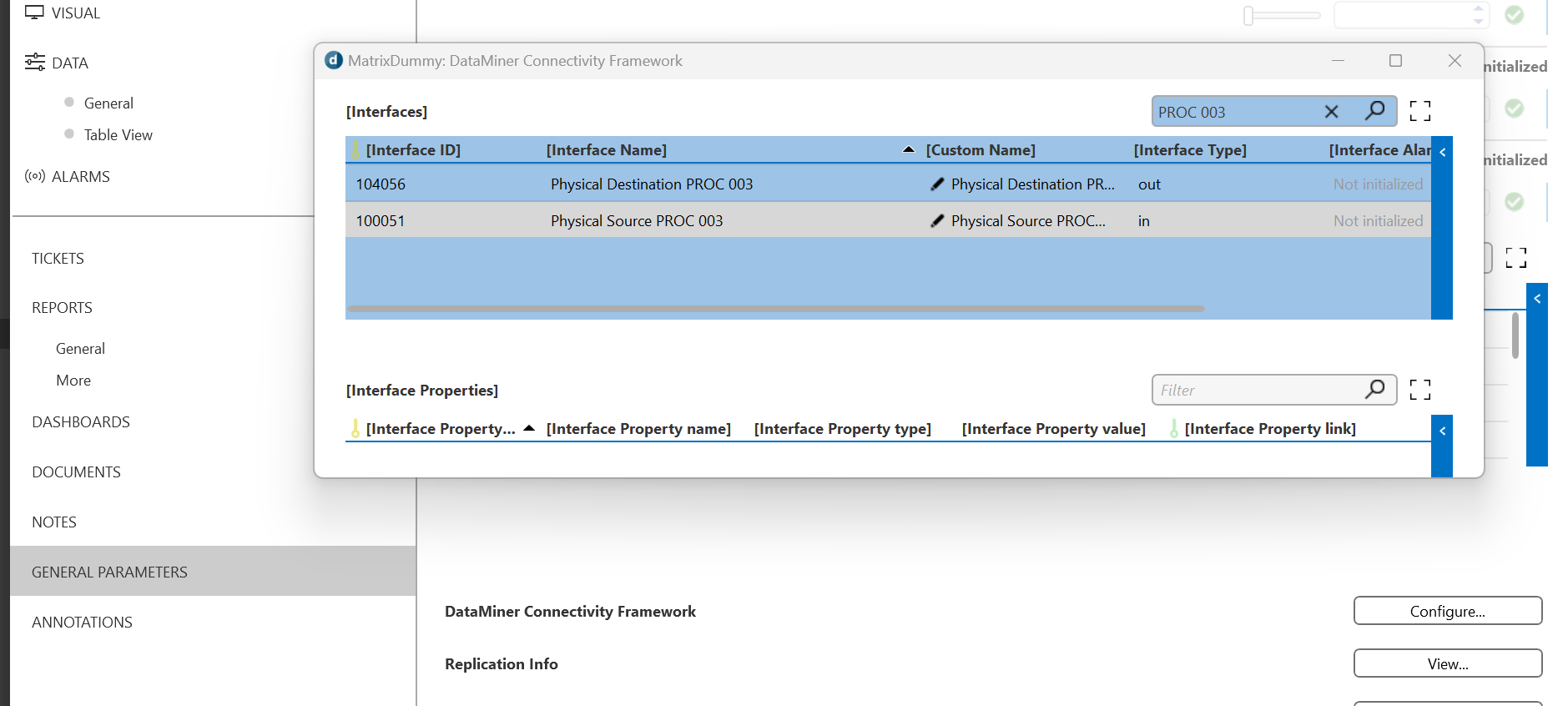
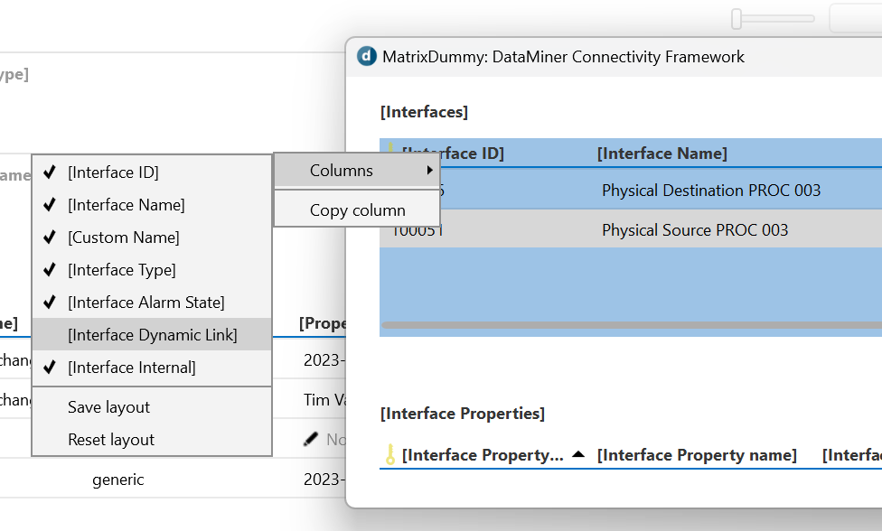
Given a DCF interface ID go to the [Interface] table (General Parameters –> DataMiner Connectivity Framework –> Configure… –> [Interfaces] (table id = 65049)

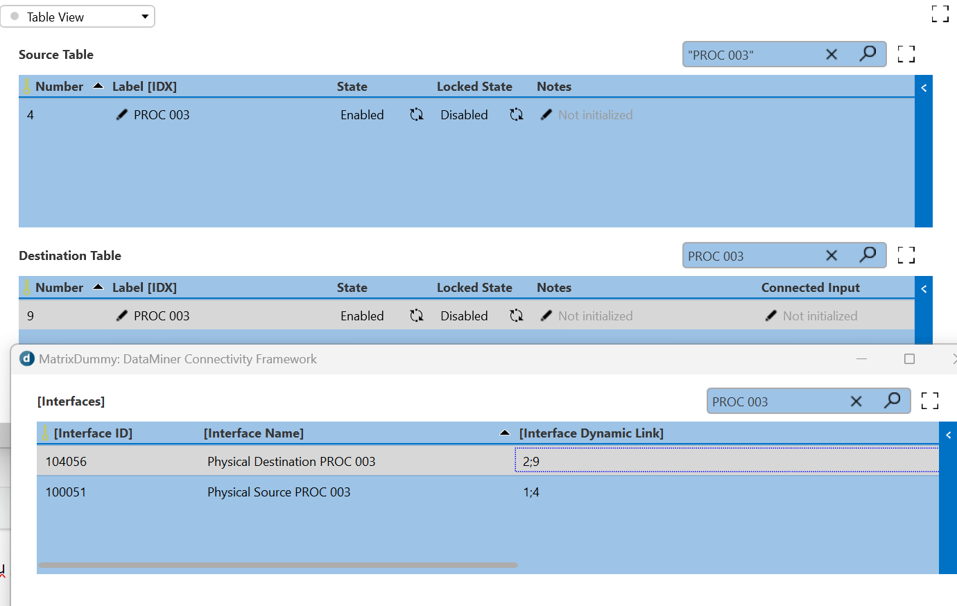
On the header enable the column [Interface Dynamic Link] id 65095, the content of the column is a semicolon seperated string.

The first part indicates if it’s an input (1) or output (2). Second part should be the i/o number of the table.


So from automation doing something like Convert.ToString(element.GetParameter(65095, <DCFInterfaceID>)).Split(‘;’)[1] should give you the index of the source or destination table
Hi Hans,
For standard matrices, the interface ID of the first output will be 100001, for subsequent output just add 1 to the number, so input two will have interface ID 100002, etc. The output numbering starts when the input numbering stops, so e.g. for a 64×64 matrix, the first input will have ID 100065.
Just for completeness of information, the first component in that parameter links to the id of the ParameterGroup associated with the matrix (see https://docs.dataminer.services/develop/schemadoc/Protocol/Protocol.ParameterGroups.html and https://docs.dataminer.services/develop/schemadoc/Protocol/Protocol.ParameterGroups.Group-id.html)
So if you were to have multiple matrixes you could use that to differentiate between Input 1 of one matrix and Input 1 of another.