Dear all,
We’re integrating monitoring for a Xicom XTCT Controller + TWTAs (HPAs), but at this point we decided to drop the Xicom XTCT-124D serial driver because of the hassle of running over 50m of cable and new RS232/485 plugs to connect the controller to the Amplifiers.
A bit something like what happened in the past…
Our problem here is that we are no longer looking at the controller, rather just monitoring the amplifiers. This is all fun and the parameters all come nicely, until we think about redundancy switching.

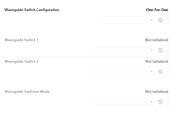
Looking at our Generic Driver:

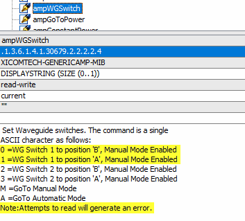
We have these parameters in each AMP to control the redundancy. First thing we notice is that these parameters are not returning any value when polled:

At this point we think about creating a redundancy group to take care of this:

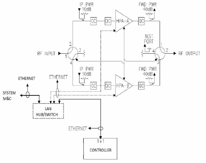
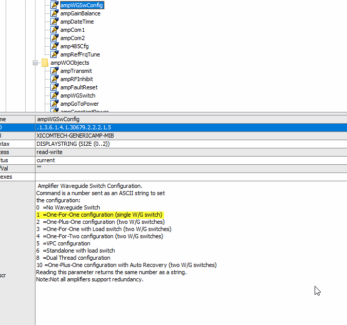
But then we spot that we have several redundancy schemes that can play a part here:

In this case we’re cool and we have only one WG switch per AMP, so the redundancy group can manage this, granted we on the Visio set the parameters properly:

The thing is that for instance if each AMP has two WG Switches, the switching between the AMP being connected to the Antenna and the other connected to Load would have to be performed via Automation Script (at least we assume so).
Questions for you all:
- Have you ever integrated a system using this driver?
- If so, how did you implement redundancy switching?
- Can you share your configurations / visios / scripts?
Thank you and apologies for the long message.
Cheers!
Hi Bruno,
When the amplifiers can’t give you the position of the RF switches, I’m afraid that there is nothing that you can do. If you would have the position of the RF switches, you can develop a virtual protocol driver to collect the RF switch information, process the information and display the result in a new parameter.
If you don’t want to work with a 50 meter serial cable, is it an option to work with an IP cable and buy a IP/serial convertor for one serial port?
Hi Koen,
Thank you for your reply.
I’ve just got in touch with the device vendor and they directed us towards a parameter that reported the switch configuration:
There is a function “ampAdvancedStatus” that reports this information.
The waveguide switch positions are indicated by the bit flags in the response to this query. If you look in page 20 of MNC-0801-001 document, you can see the definitions for all the bit flags.
Byte 4 of the bit flags shows the waveguide switch positions.
OID: .1.3.6.1.4.1.30679.2.2.2.3.10
Which is currently not implemented in the Generic Driver.
In any case, other experiences of our colleagues with this integration are welcome here.
Thanks!