example Use Case
DataMiner Virtual Matrix (vMatrix)
2110
SDI
ASI
RF
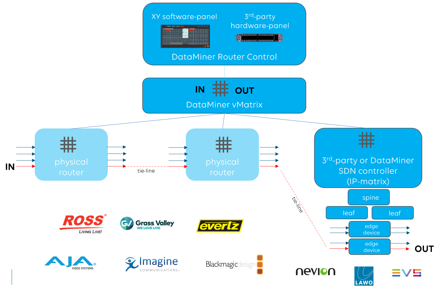
This use case demonstrates how DataMiner can put a virtual matrix on top of one or more third-party routers (matrices) and how connections across those can be managed.
The DataMiner virtual matrix is not limited to traditional third-party SDI, RF or ASI routers but also interfaces with any third-party SDN controller of your choice. You can even combine it with DataMiner’s SDN orchestrator to build a true hybrid routing solution.
With the vMatrix, you can set crosspoints ad hoc, for instance via a simple XY software routing panel, but also schedule crosspoints ahead of time. Together with multi-label support, built-in tie-line management and label management, the DataMiner vMatrix supports your signal routing requirements.
USE CASE DETAILS
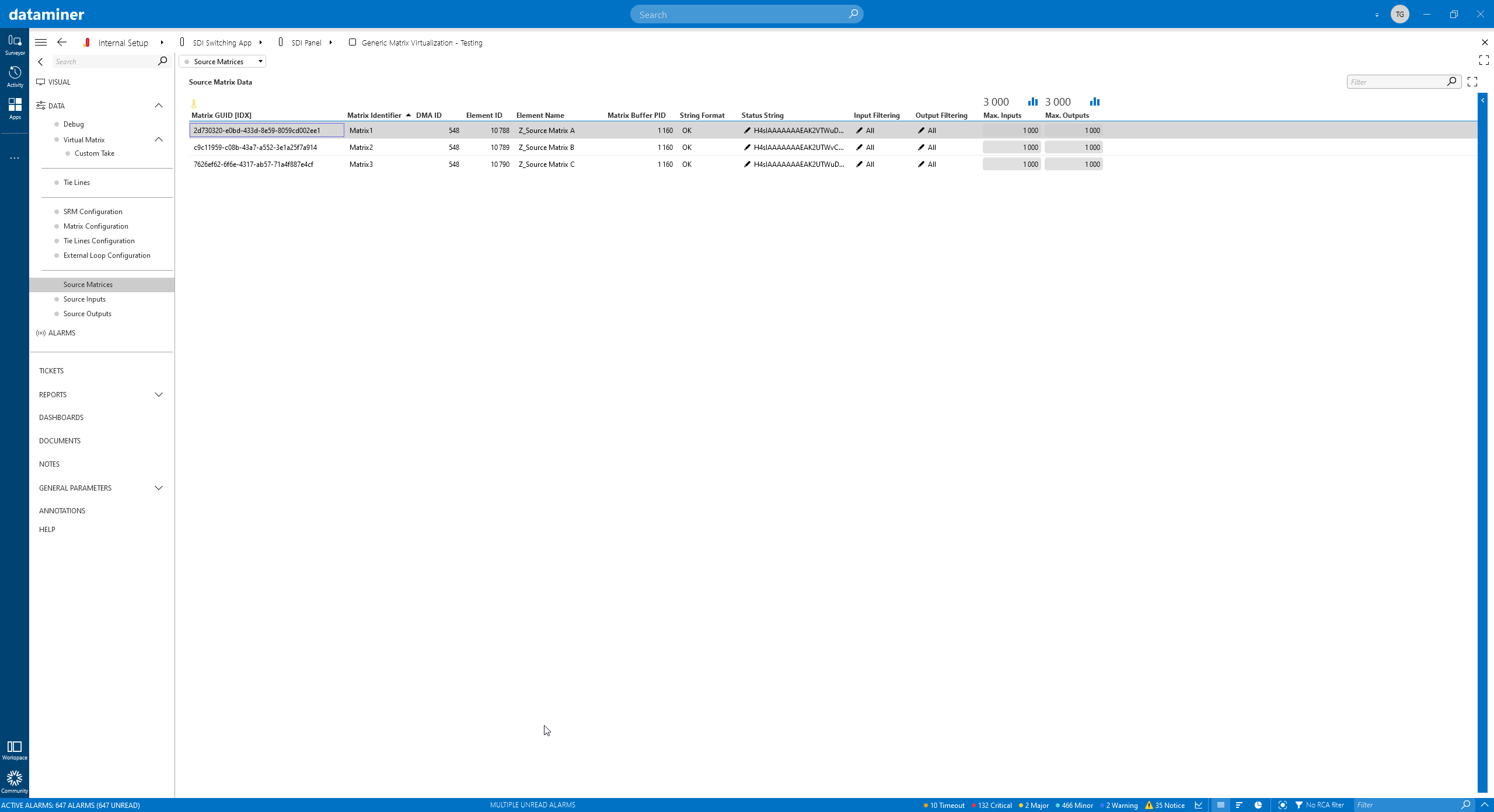 To start with the DataMiner virtual matrix, all the physical matrices or SDN controllers get added. You can also filter out certain inputs and outputs and only add a subset of all IOs available in a matrix.
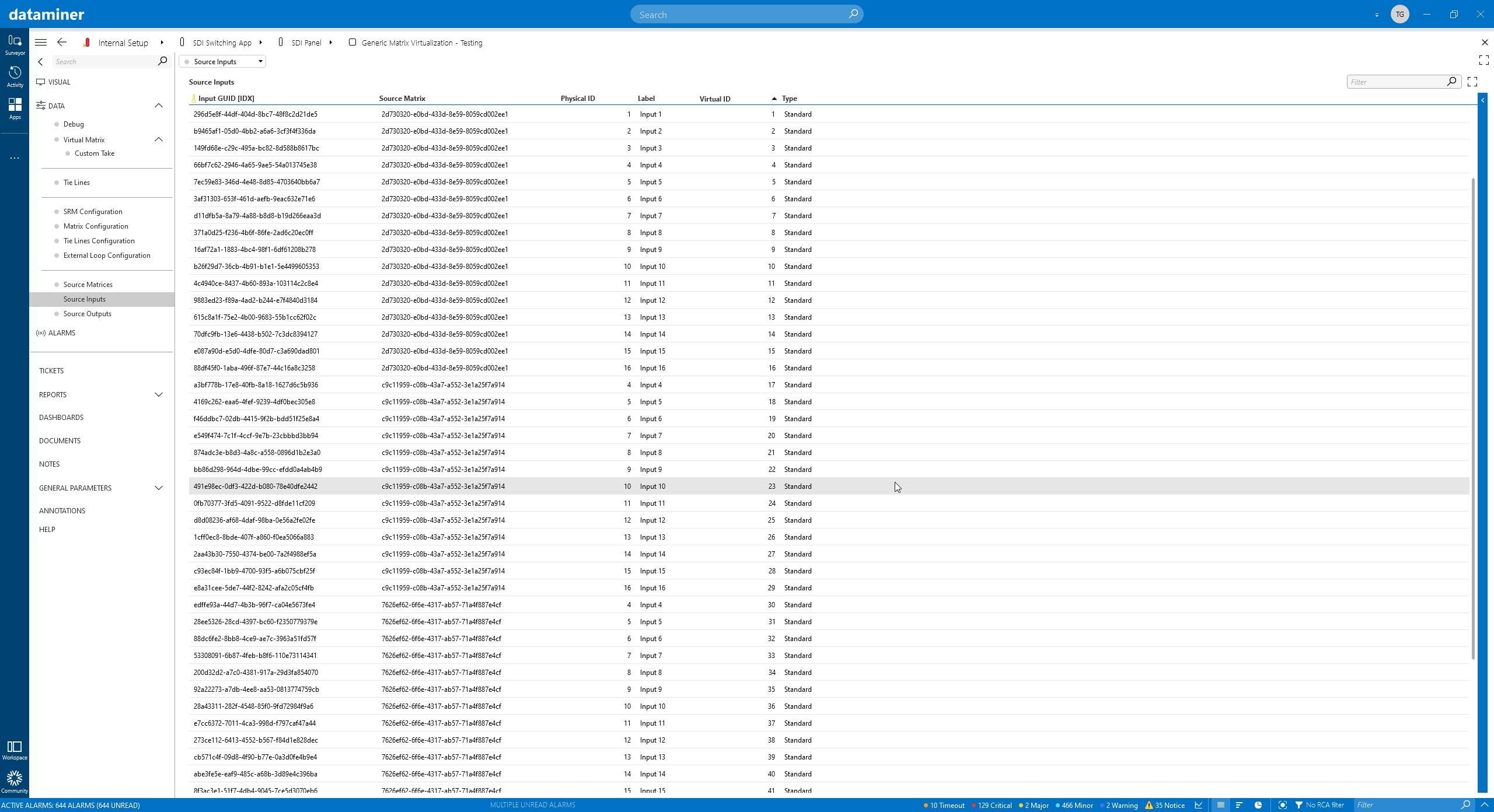 In a next step, each physical input of each matrix will be mapped to a virtual input of the DataMiner vMatrix.
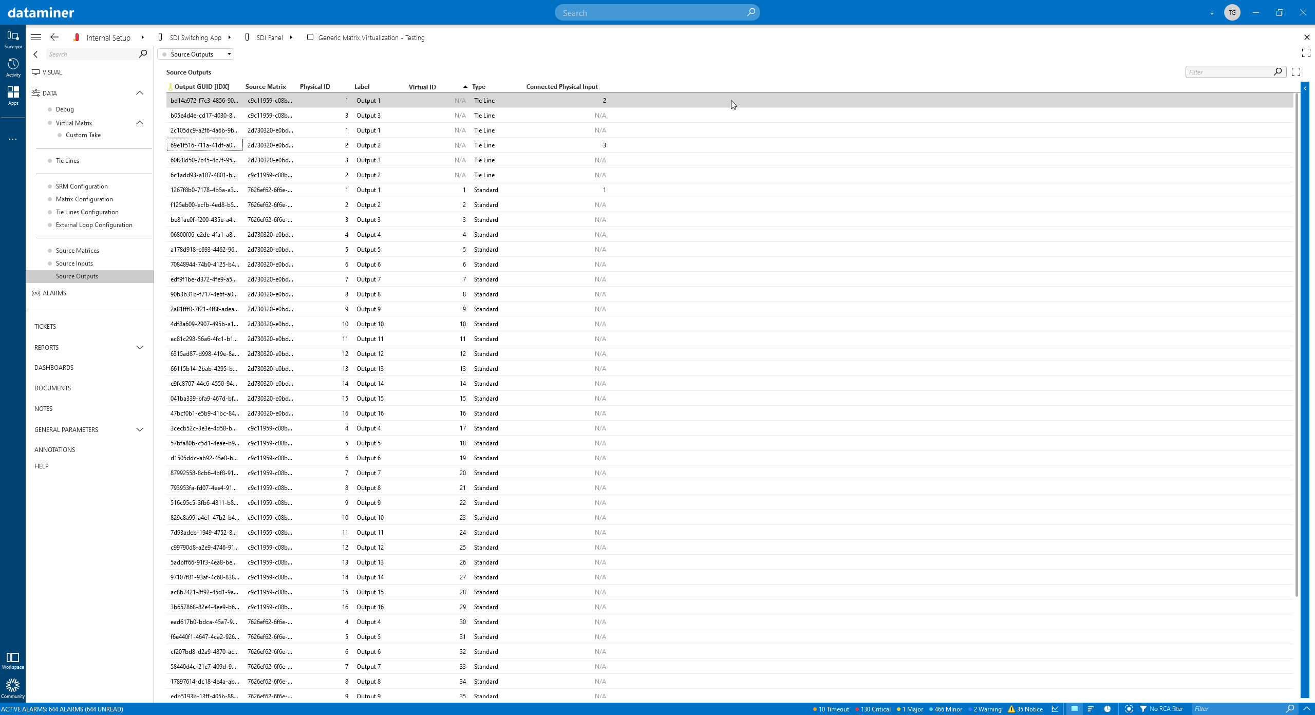 The same goes for the outputs.
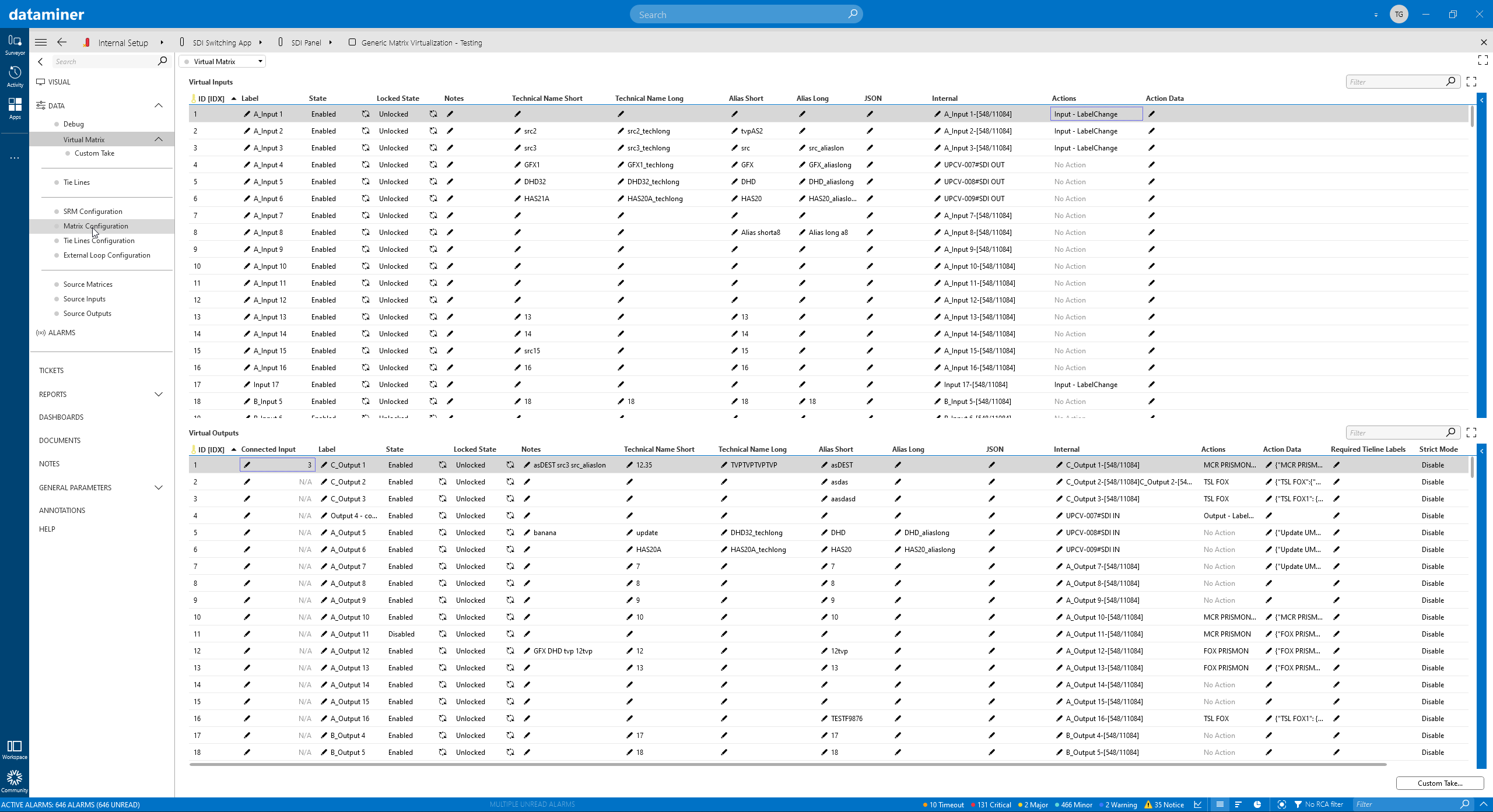 Once the physical matrices have been added, the DataMiner vMatrix is represented by IO tables. Each IO from the virtual matrix is mapped to a specific IO on one of the physical matrices or SDN controllers. For each virtual output, DataMiner knows if a virtual input is connected.
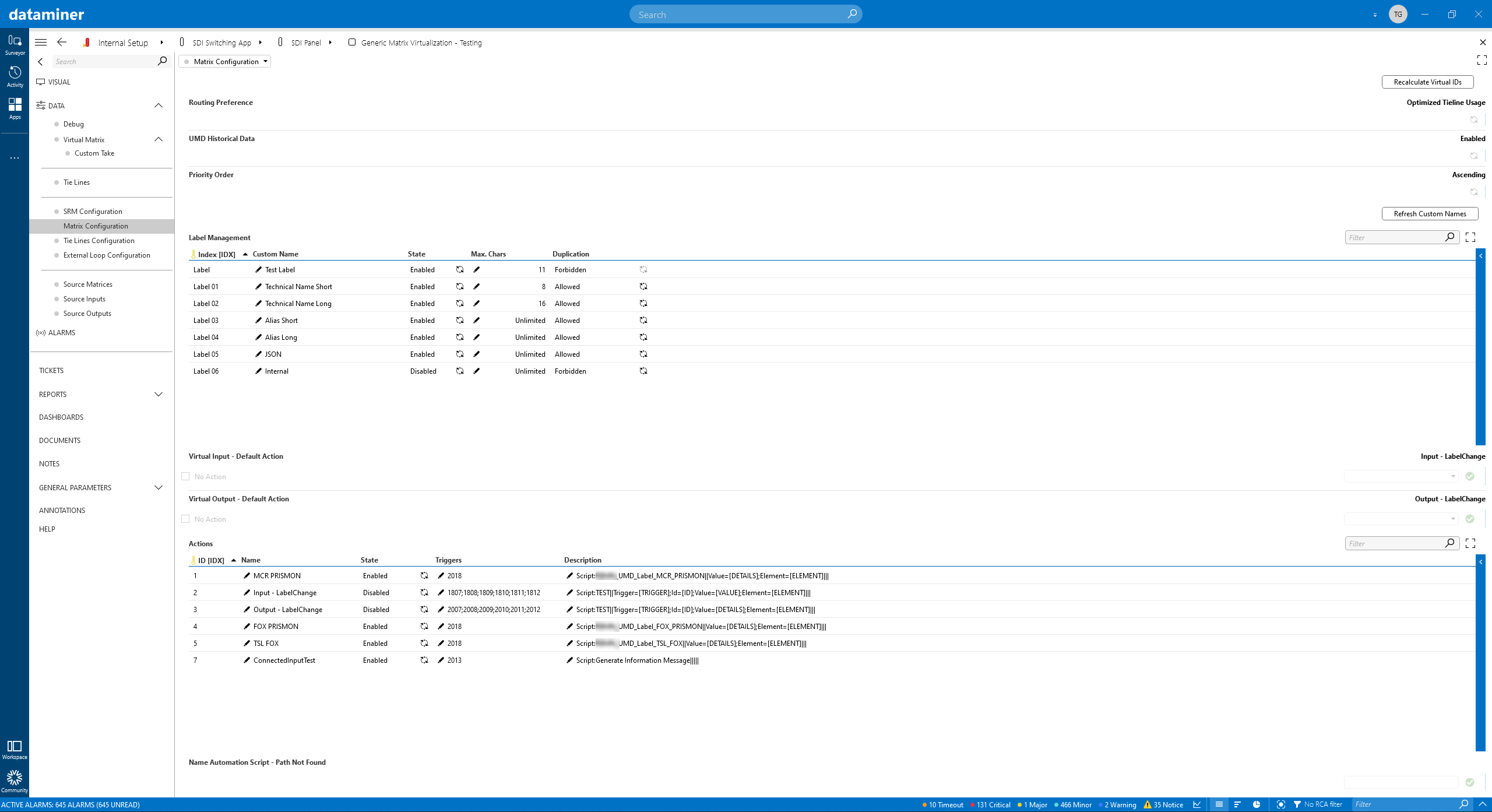 Each IO can be given one or multiple labels. You can define the maximum length per label and specify if duplicate label names are allowed.
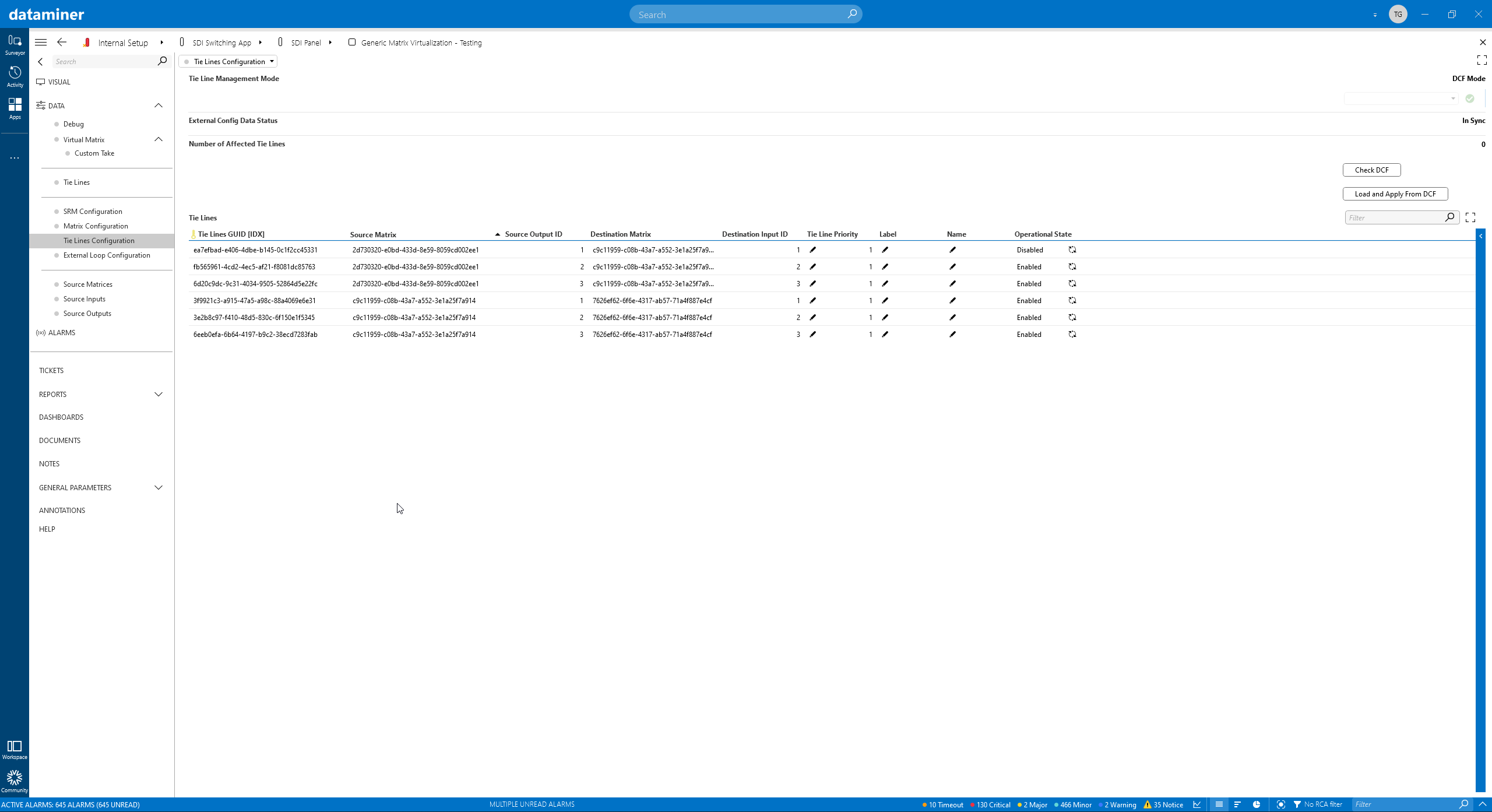 The vMatrix manages tie lines between your routers. This screenshot shows the defined tie lines. With DataMiner you can either specify tie lines manually or let them be created automatically based on the DataMiner Connectivity Framework (DCF).
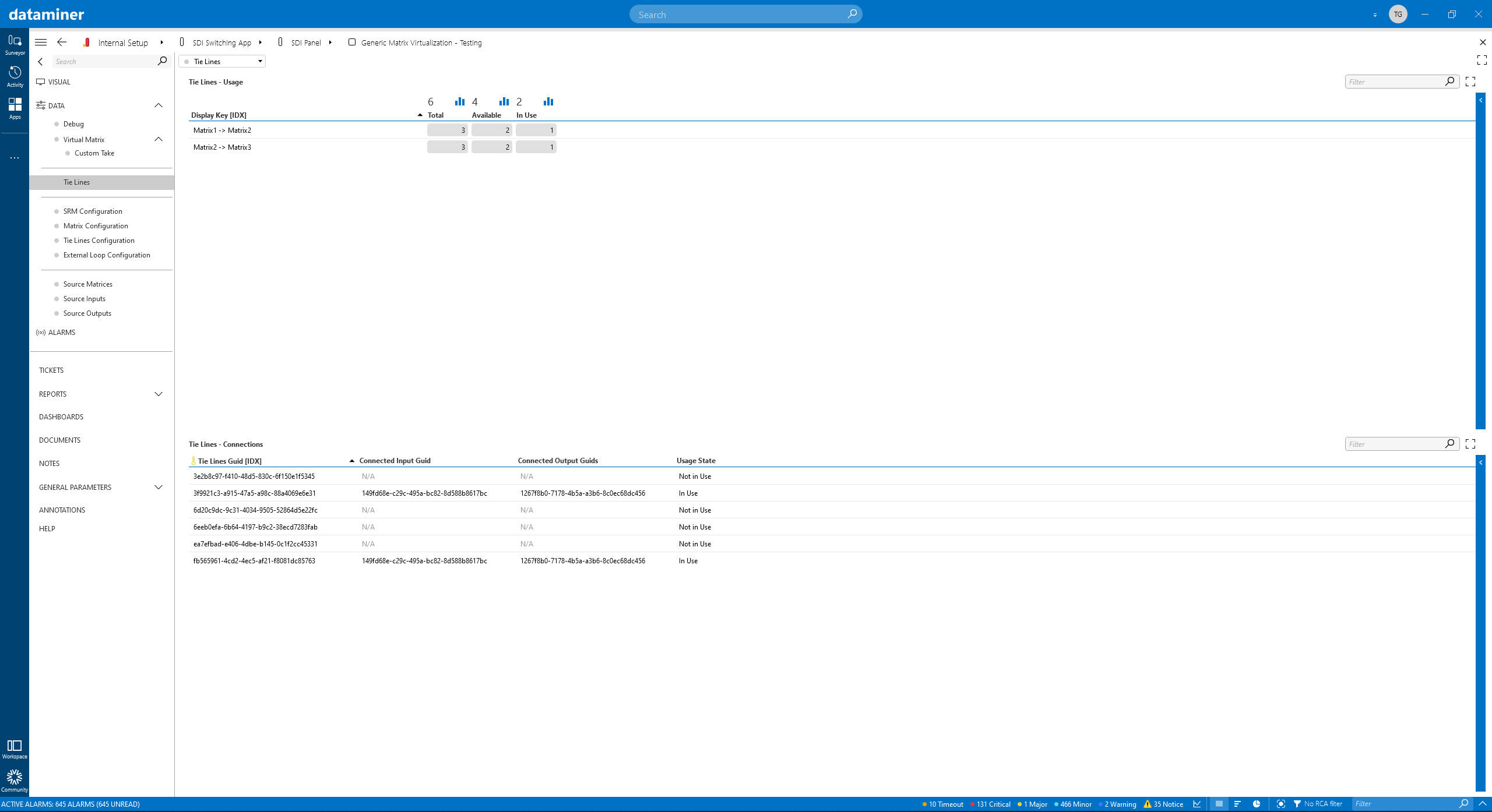 Once tie lines have been configured, DataMiner knows about the total number of tie lines between matrices and constantly tracks the ones in use and the ones that are still available.
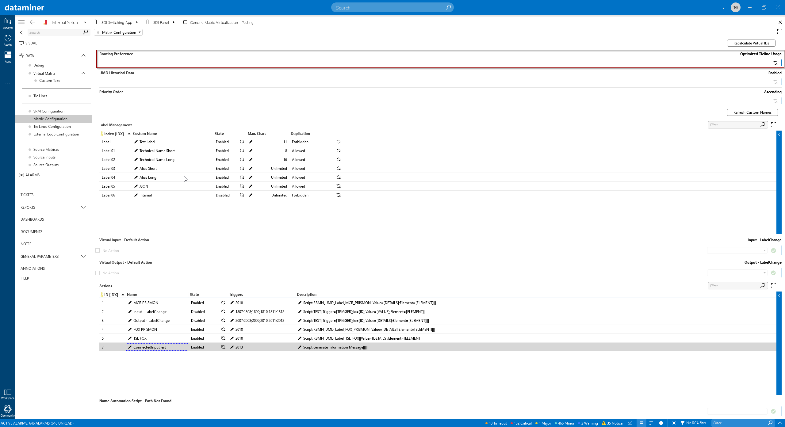 Tie lines can be calculated in two different ways. "Optimized tie line usage" will reuse tie lines that are already transferring the required signal between two matrices. For a large-scale routing environment, "shortest path" might be the right option. The latter will use the shortest path between a source and destination, based on the number of hops. When you run out of tie lines, the vMatrix allows you to run a custom script to perform any kind of logic, starting from a failure message up to a complex workflow, for example to free up a tie line that is used for a less important signal.
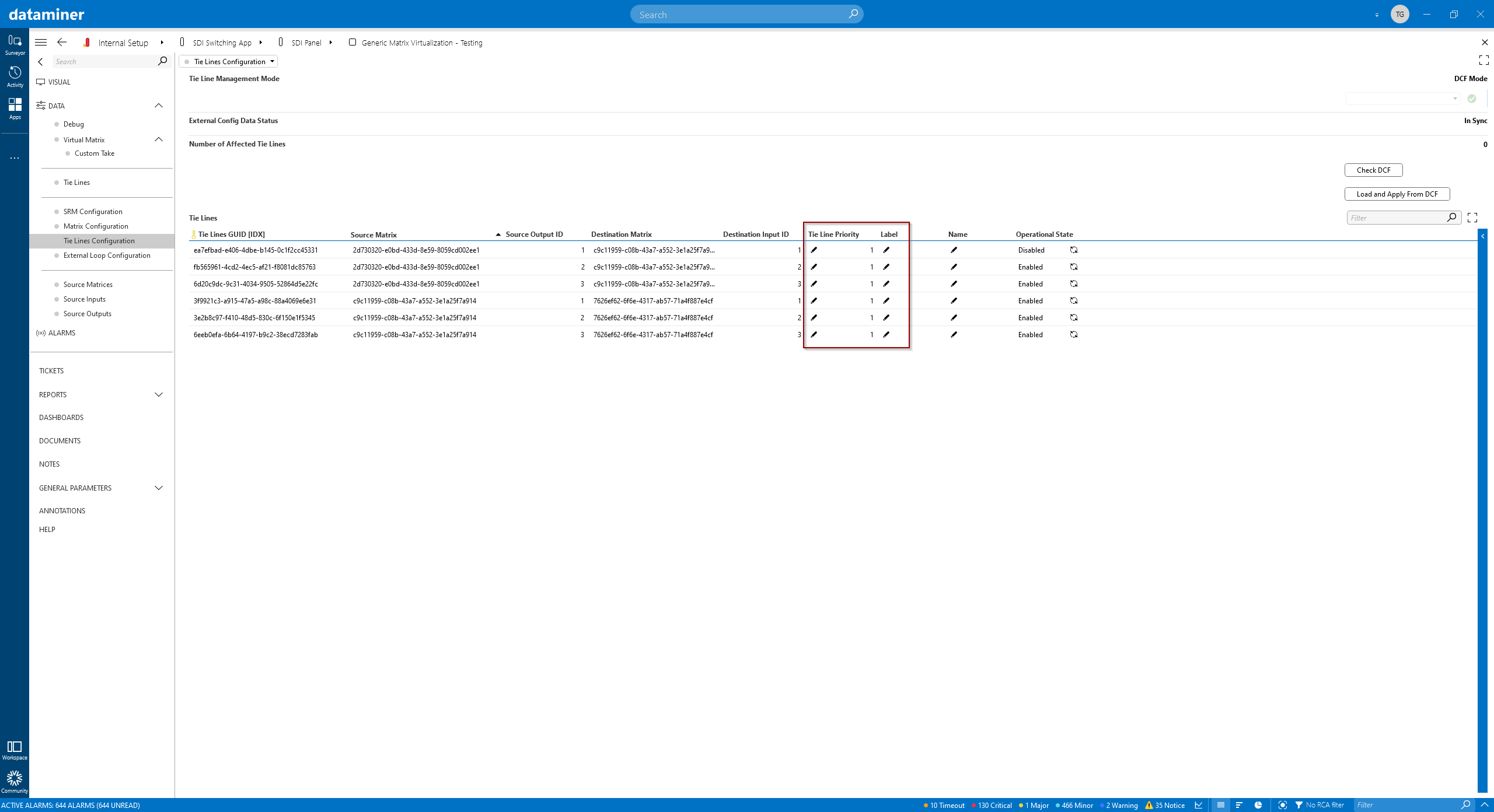 You can also define priorities for each tie line. The one with the highest priority will be selected first. As you can see in the image, you can also indicate labels per tie line. Those labels can then be linked to a virtual output to define that only those tie lines will be selected to route a signal. This is a great feature to "reserve" tie lines for highly important destinations, for example your on-air signals.
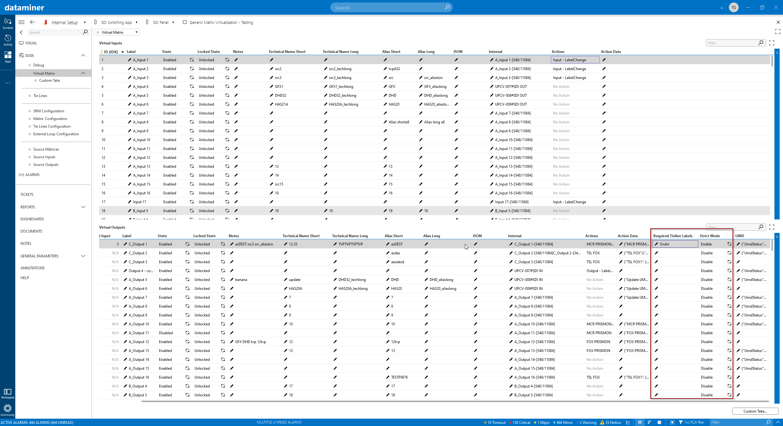 This image shows where you can define the required tie lines labels. With the "strict mode" enabled, only labeled tie lines can be used, otherwise tie lines can also be used if they don't have a label.
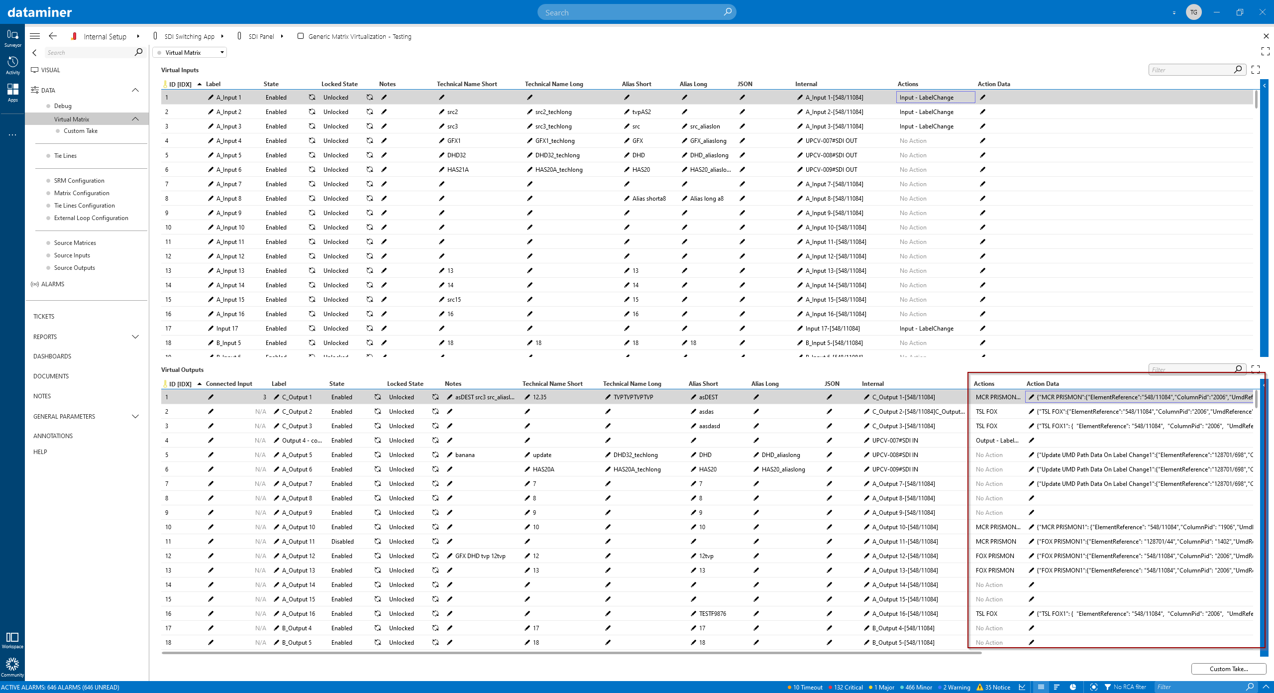 The DataMiner vMatrix has been built in such a way that a crosspoint command can trigger any additional action, for example to set a UMD label. This is done by triggering Automation Scripts that can set the UMD label on any device, via any protocol, for example the widely used TSL protocol. Labels for UMDs are not limited to the connected source label. Custom rules can be set to dynamically create the string for the UMD. As the vMatrix knows the connectivity from the source across all processing units and tie lines up to the destination, this info can be used to create a concatenated UMD string. This can for example be used to show the short technical name of the source, then its long alias, and after that the short names of all processing units from source to destination. As a result, the label could be something like this: "IN1 LIVE1 GFX2 UC3 DOLBY4".
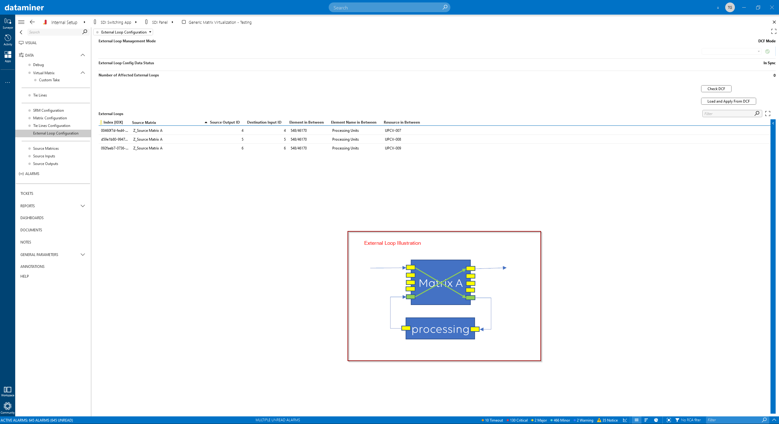 To be able to identify a complete signal chain from source to destination, the vMatrix keeps tracks of "external loops". Those are typically processing units, e.g. a video delay, that were inserted into the signal chain. To identify those external loops automatically, the DataMiner Connectivity Framework (DCF) is used. This info can now be used to create a UMD label that includes the looped-in processing unit.
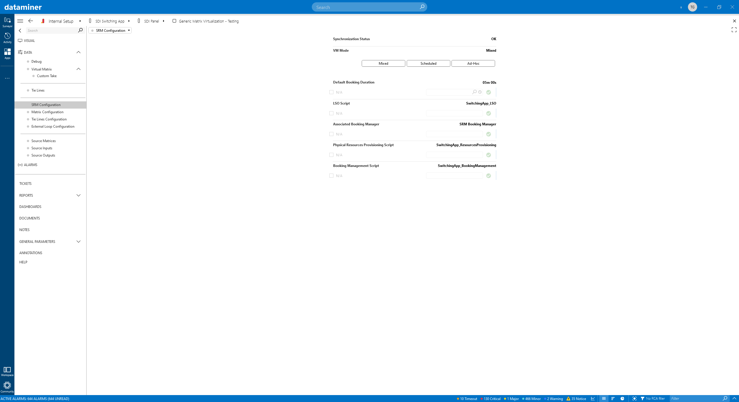 Up to now, we were only looking into ad-hoc signal routing. The DataMiner vMatrix also ties into the DataMiner Service and Resource Management (SRM) suite of tools to support any kind of service that needs to be booked ahead of time. Using the vMatrix "scheduled mode", a DataMiner booking can be created for a connection: inputs, outputs and tie line resources will be reserved. With this, you will be assured that your signal can be routed when you need it in the future, and you don't have to worry if there will be sufficient tie lines available. And last but not least, the "mixed mode" combines both worlds.
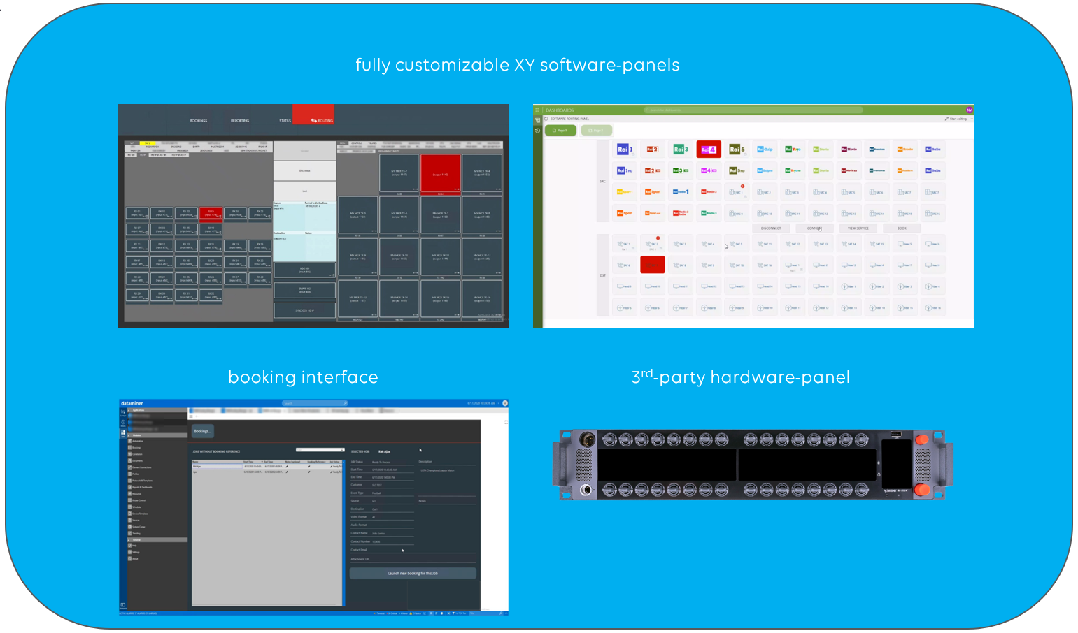 Wondering what our software router control surfaces and third-party hardware-panel integrations look like? You can find many examples in our use case library (via Discover > Use Case Library) – just filter on "router panel" with the box on the left.