solution Use Case
Uplink auto monitoring workflow
RF
Satellite Uplink
Double D Electronics
Miteq
Tektronix
Ericsson
DataMiner is used to replace a legacy Uplink Terminal M&C system.
The main goals include:
- Simplifying operational screens to provide only critical control.
- Introducing detailed status and control screens for engineering support.
- Automating the monitoring process to reduce fault recovery times.
This involves:- Automating uplink chain monitoring
- Automating service monitoring
- Automating service restoration
DataMiner operates in a broadcaster’s uplink facility across two similar geo-redundant sites, integrating several subsystems such as receive, transmit, diversity switching, and modulation.
Each site consists of separate uplink terminals for two Astra satellites, with only a single active terminal per satellite at any given time.
DataMiner accommodates the following functions for each terminal:
- Automated uplink chain monitoring
Each uplink terminal is capable of transmitting up to 8+1 chains per polarization, totaling up to 18 chains. DataMiner automatically iterates through these chains to verify signal presence and validate detected services at the output of each chain. This is also performed on the offline chain, to ensure constant readiness for transmission. During the round-robin process, a single IRD is tuned to the ‘under-monitoring’ chain using configuration parameters stored in a reference database and live parameters fetched from the uplink equipment. Any anomalies and errors are automatically reported to the operator. - Manual monitoring
For in-depth investigations, the engineering team can manually select a chain and analyze the output at either the KPA or upconverter. They are also able to check the matching downlink signal via a dedicated IRD. - Diversity switching
A hardware diversity switching controller takes care of switching between the two geo-redundant sites. DataMiner provides visibility on the status and also allows the operator to perform a manual switchover if needed.
The visual layer incorporates both Visual Overview drawings, mainly for technical engineering schematics, and Low-Code Apps.
USE CASE DETAILS
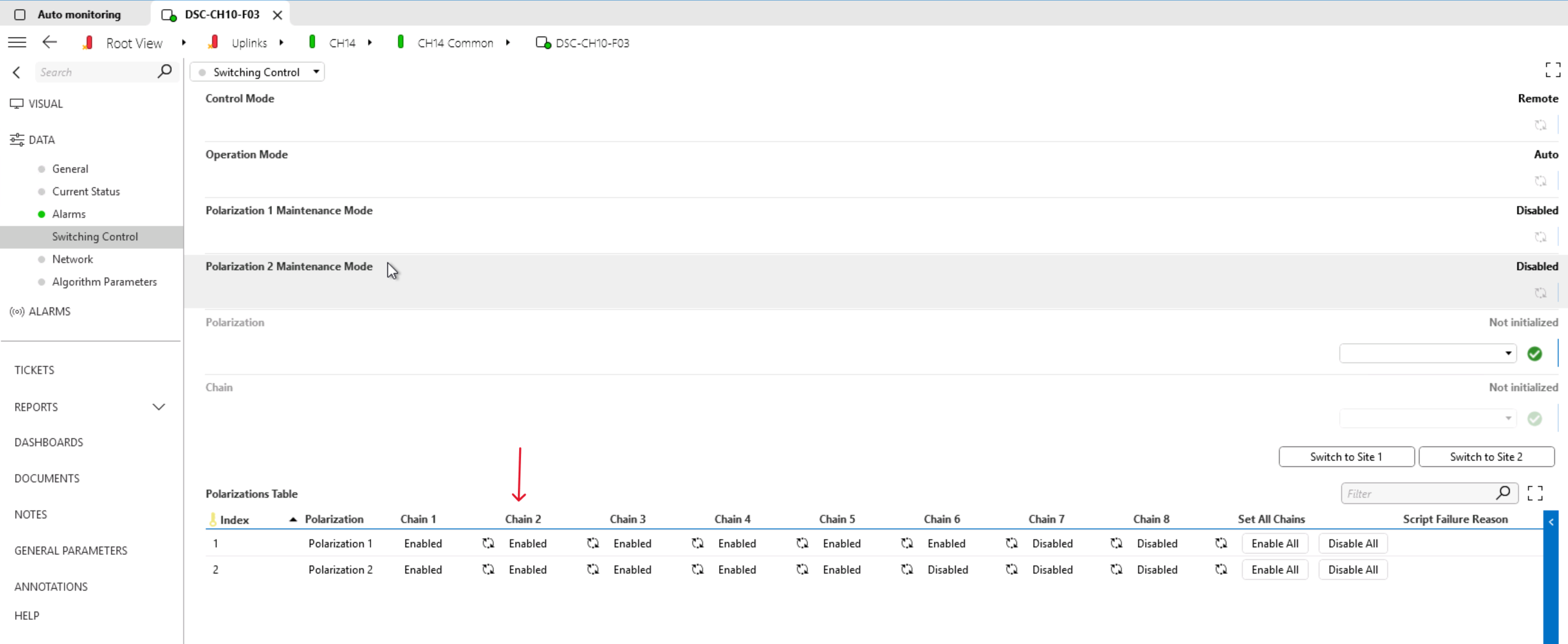 The diversity controller element (DDA 266) is being probed to check which chains are active, for both horizontal and vertical polarization chains. We will monitor only the active chains.
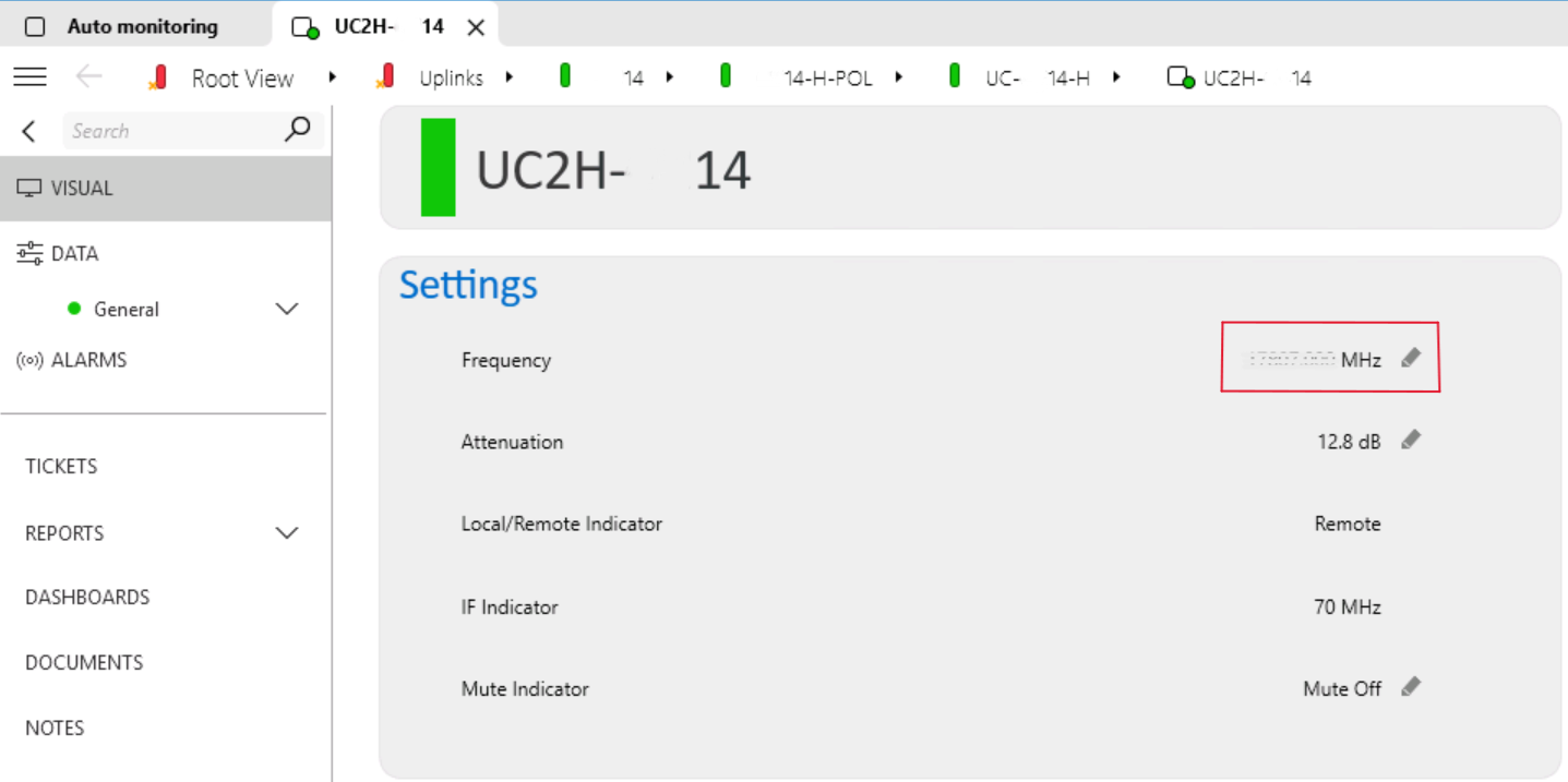 This device shifts the frequency of a signal to a level suitable for satellite transmission. An example of an active chain is the second chain with V polarization. You can also find the corresponding upconverter element and read the frequency.
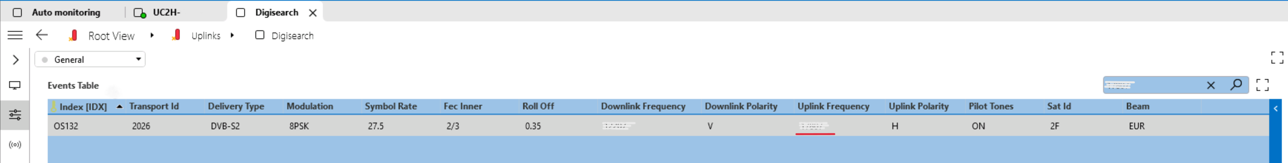 Here you can see how a connector retrieves the IRD tuning parameters from the internal database "digisearch" by matching the uplink frequency with the one found in the corresponding upconverter.
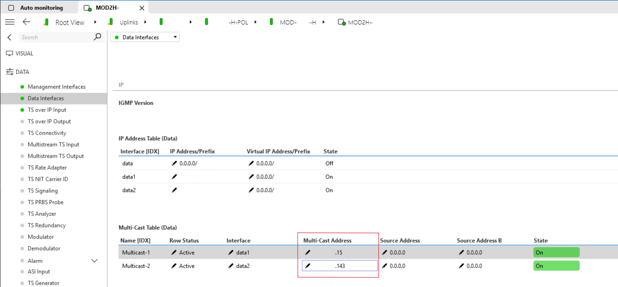 Modulators convert digital signals into a format suitable for radio frequency transmission. They employ various techniques to optimize signal quality and resistance against noise and interference during transmission. The corresponding modulator element is probed to identify the main and redundancy multi-cast IP addresses.
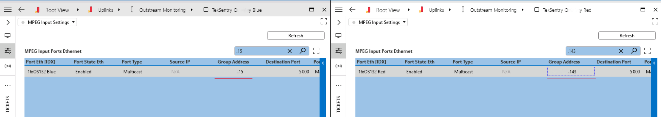 The Tektronix Sentry device ensures quality assurance and monitoring in digital video broadcasting and streaming environments.
By filtering out the IP addresses handled by Sentry elements, you can verify the correct usage of output stream numbers. You can also see which site handles this stream.
The Tektronix Sentry device ensures quality assurance and monitoring in digital video broadcasting and streaming environments.
By filtering out the IP addresses handled by Sentry elements, you can verify the correct usage of output stream numbers. You can also see which site handles this stream.
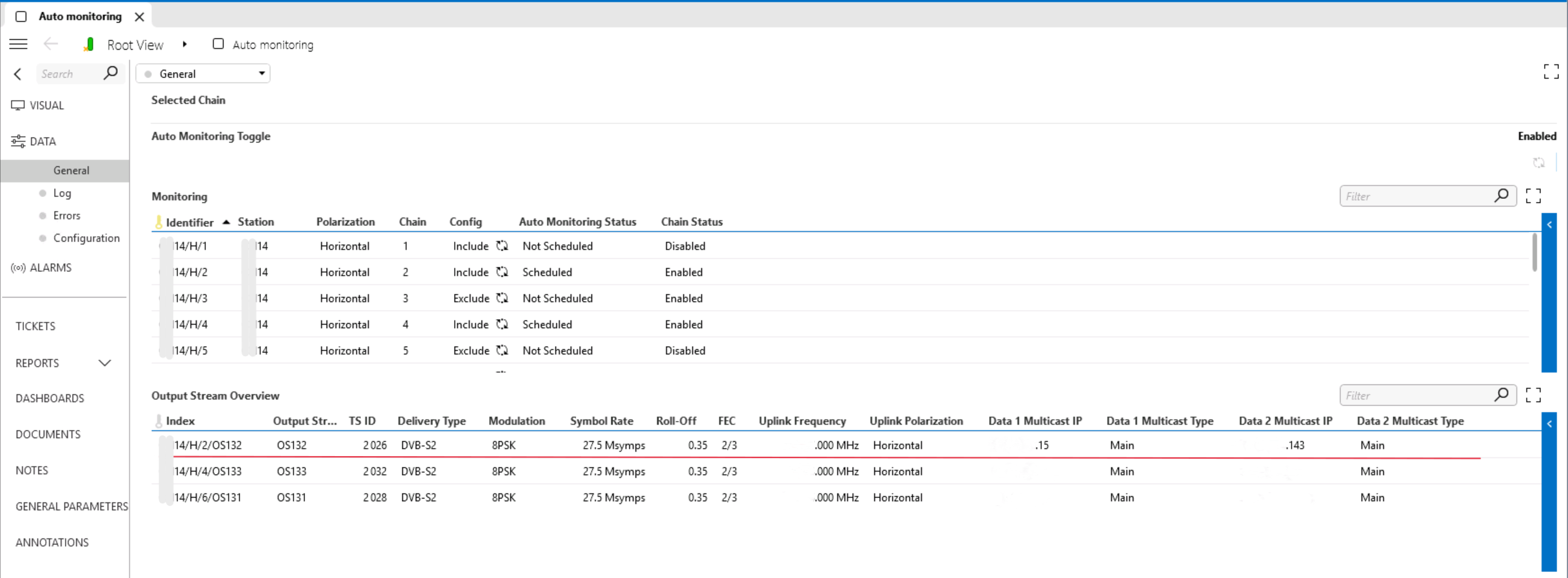 The connector displays all the relevant data for monitored chains. Operators can find all the data from previous steps in this table. This data is used to tune the IRD.
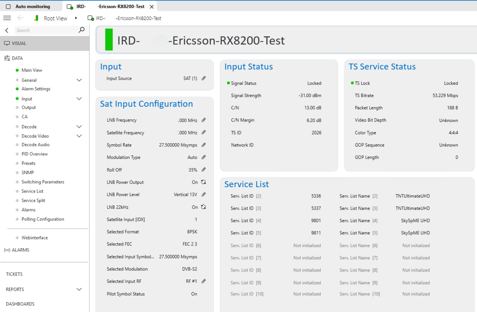
 The preselected IRD is tuned with the right parameters. Now the operator should verify if the IRD has successfully locked onto the signal, ensure the transport stream ID is OK, and cross-check the service list handled by this uplink chain.
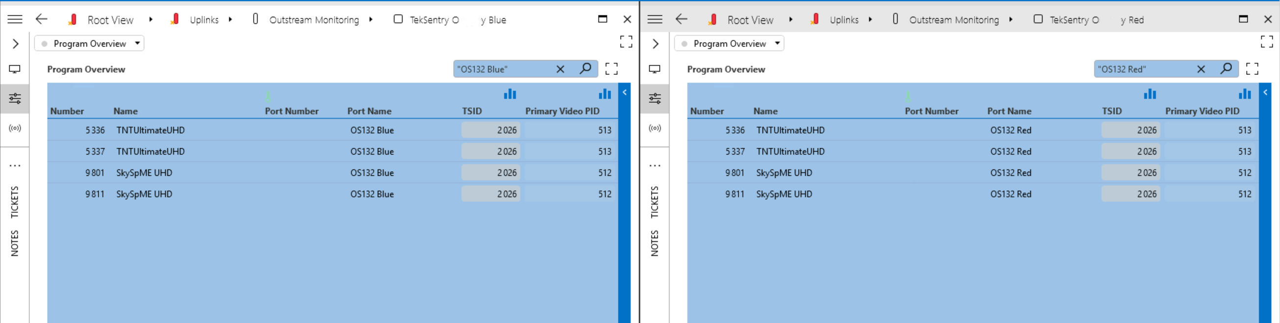 With the service list obtained from the IRD, when comparing lists, both the names and the IDs should match on the main and redundant Sentry and the IRD.
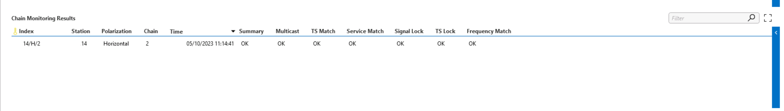 Here you see a final summary table that outlines the entire process, highlighting any inconsistencies along the way. In such a case, operators can easily find the root cause of the problem and get the system back on track.
7 thoughts on “Uplink auto monitoring workflow”
Leave a Reply
You must be logged in to post a comment.
Efficiency is always welcome!!
Great Use Case Benjamin!
Great one Benjamin 😉
Good job Benjamin!
Well done Benjamin!
Great!